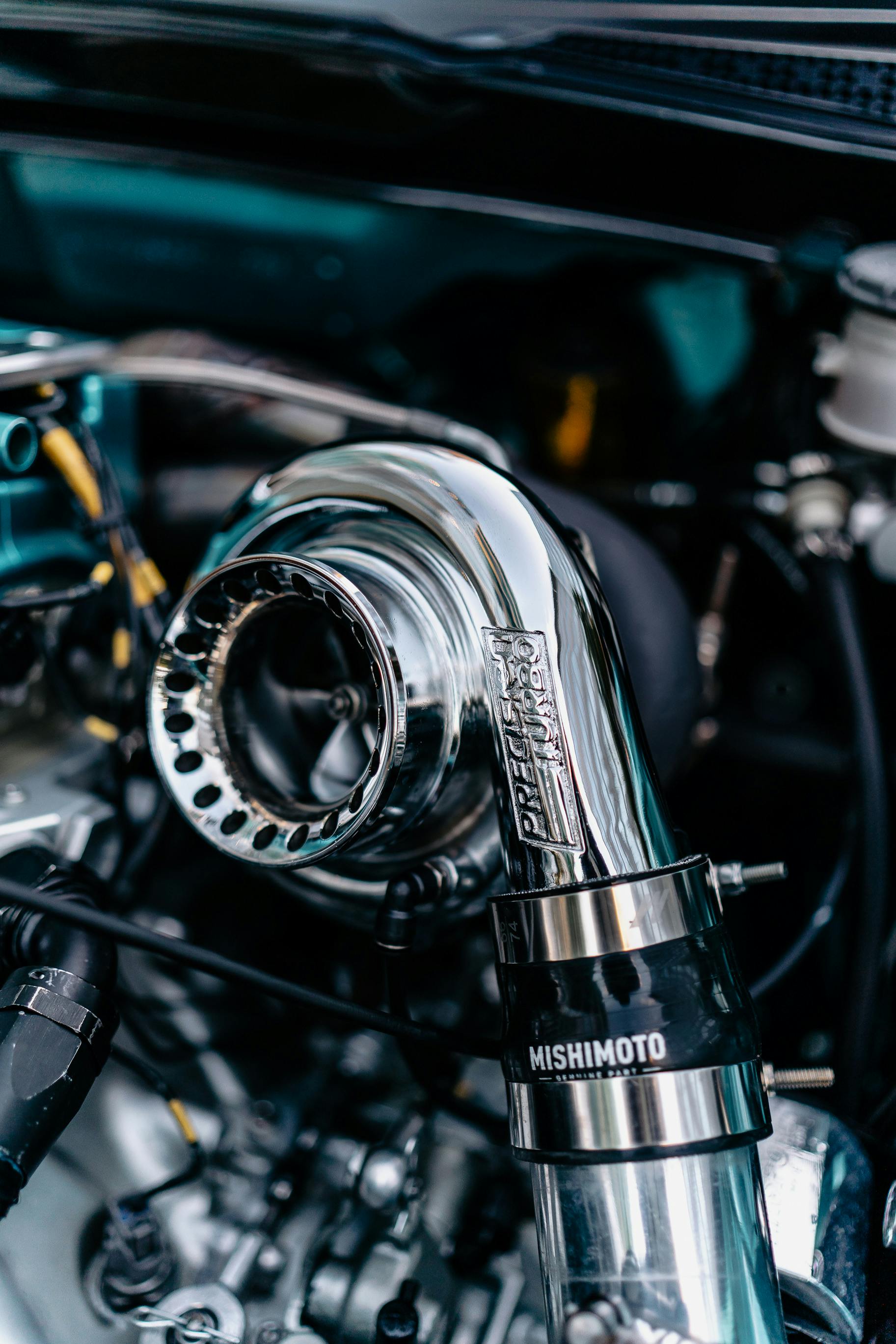
In the world of high-performance automotive engineering, the turbocharger stands as a marvel, a true heart of the engine that transforms ordinary vehicles into powerhouses of efficiency and exhilarating performance. It’s a sophisticated air pump, designed to compress the intake air, allowing more fuel to be added for a greater explosion of power, all while harnessing the energy of the engine’s exhaust gases. Operating at mind-boggling speeds—often between 80,000 to 200,000 rpm, and sometimes even up to 250,000 rpm—this critical component is central to both modern vehicle design and the thrill of the drive. The intricate interplay of its compressor, turbine, and bearing systems, all lubricated by the engine’s oil, demands precision and robust design. However, like any high-stress component, turbochargers are susceptible to a range of failures that can occur well before their anticipated service life, often with catastrophic consequences for the entire engine system.
Understanding what can cause a turbocharger to fail is not merely an exercise in diagnosis; it’s a vital step towards owning, operating, and maintaining your turbocharged vehicle with greater success and longevity. While the array of potential problems can seem daunting, a systematic approach, much like a medical autopsy, can pinpoint the root cause, allowing for corrective measures to prevent repeat failures. For the uninitiated, determining the initial point of failure amidst widespread damage can be extremely puzzling. Yet, trained technicians can meticulously analyze components and environmental factors to reveal the likely culprit. This deep dive aims to demystify turbocharger failures, providing automotive enthusiasts and professionals alike with authoritative, factual, and detailed insights into what goes wrong when these high-speed marvels give up the ghost prematurely. We delve into the most common and critical failure modes, offering a clear, structured guide to understanding these complex issues.
Indeed, while there are numerous reasons for turbocharger failure, experience shows that approximately 20 percent of these reasons account for 80 percent or more of the failures that occur. By focusing on these prevalent causes, we equip you with the knowledge to better protect your investment and maintain peak performance. Let’s unpack the primary culprits behind unexpected turbocharger breakdowns, beginning with the most direct forms of physical trauma and working our way through lubrication and thermal challenges. These are the critical lessons gleaned from years of real-world application and failure analysis, essential for anyone passionate about turbocharged power.

1. **Foreign Object Damage (FOD) – Compressor Side**Foreign object damage (FOD) to the compressor side of a turbocharger is often one of the most obvious and quickest diagnoses in failure analysis. This type of damage occurs when external debris or unintended objects are ingested into the turbocharger’s intake system, impacting the delicate compressor wheel. The consequences are immediate and often severe, leading to an imbalanced turbo that can rapidly self-destruct.
The typical culprits behind compressor-side FOD are varied and sometimes surprising. Common items include threaded fasteners, nuts, or bolts inadvertently dropped during maintenance or assembly. Mechanic’s shop rags left in the air intake, wrenches, or other tools that found their way into the system are also seen. Furthermore, parts of a failed air cleaner, perhaps a filter that was too small or extremely dirty, can disintegrate and be drawn into the compressor. Rocks and other airborne abrasives, allowed to enter due to a missing or failed air filter, can also cause significant trauma.
Upon external examination, an ingested foreign object will leave distinct telltale signs. The leading edge of the compressor blades, known as the inducer, will display obvious impact traumas. Pockmarks around the compressor cover inducer area, leading into the compressor wheel, indicate where an object bounced around before finally entering the wheel. If the engine is equipped with a charge-air aftercooler, the foreign object, or parts of it, might even be found lodged within the cooler. These aftercoolers, with their small tubes and turbulators, often act as a catch net, preventing further damage to the engine itself by filtering out small particles. While it’s advisable to remove and reverse flush the cooler to dislodge any remaining parts, it’s a clear indicator of this specific failure mode.

2. **Foreign Object Damage (FOD) – Turbine Side**While foreign object damage (FOD) to the compressor side is often visible and easily traceable, FOD on the turbine side presents a different set of challenges. This occurs when objects enter the exhaust stream and impact the turbine wheel, leading to similar catastrophic damage as on the compressor side, including imbalance and structural failure. However, the source and nature of these objects can be more internal and elusive to diagnose.
Turbine wheel inducer impact traumas, when the compressor wheel shows no signs of FOD, often signal internal engine damage. Fragments from failed valves or pistons are common turbine wheel eaters. These metallic shards typically do not remain in the exhaust system long enough to be easily found, as they pass through the wheel while causing damage and lodge downstream. In cases of a failed valve, the driver would likely have noticed a significant drop in engine performance prior to the turbocharger giving out. For high-performance applications like drag cars, these incidents can occur almost simultaneously, making differentiation extremely difficult in the heat of the moment.
Beyond internal engine fragments, external objects can also find their way into the turbine housing. A shop rag mistakenly left in the exhaust manifold during service, threaded fasteners inadvertently dropped into the manifold, or fragments from heat baffles or other exhaust manifold components can all cause severe damage. Inspecting the exhaust manifold or header system for such lingering objects is a critical step in a conclusive diagnosis. Understanding the characteristic differences between impact trauma and other forms of turbine wheel failure, such as overspeed or over-temperature, is crucial for accurate assessment, ensuring that the true cause is identified and corrected.

3. **Contaminated Lube Oil**Contaminated lube oil stands as one of the most frequent and insidious causes of turbocharger failure. The turbocharger’s demanding rotational speeds, coupled with its reliance on the engine’s lubricating oil for both cooling and bearing support, make it exceptionally vulnerable to any degradation in oil quality. When the lubricating oil becomes abrasive or sludgy, it directly attacks the precision components of the turbocharger, leading to premature wear and eventual failure.
The primary drivers of oil contamination are typically severe operating environments where a large amount of dirt or abrasive particles can enter the air intake, or, more commonly, infrequent and inadequate oil changes. As a turbocharger is not a completely sealed system, exhaust gases can seep into the bearing housing over time, introducing carbon deposits into the oil. If oil changes are neglected, these carbon deposits gradually build up, transforming the oil into a thick, sludgy residue that drastically reduces flow and increases its abrasive properties. This sludgy concoction then causes excessive wear to crucial turbo components, leading to increased movement in the bearing assembly and, in extreme cases, contact between rotating and stationary parts.
The symptoms of contaminated lube oil are distinct and widespread throughout the turbocharger’s bearing system. These include wear on the journal bearing’s outer and inner diameters, significant thrust bearing surface wear, and scoring on the turbine shaft. Ultimately, the wheels may rub against their respective housings as the bearings wear down. The common particles found in engine oil that lead to such failures range from cleaning shot, grit, or glass beads—often residues from overhaul—to brazing flux, sand, airborne dirt, or metallic debris separating from other failing engine components. An oil analysis is highly recommended in such cases not only to confirm the turbo failure cause but also to determine if the engine itself is at risk, preventing far more severe and costly damage.
Read more about: Unlock Showroom Shine: The Ultimate Popular Mechanics Guide to Washing and Waxing Your Car for Lasting Paint Protection
4. **Lack of Lubrication (Oil Starvation)**Even with an apparently healthy engine and adequate oil levels, a turbocharger can suddenly suffer from a catastrophic lack of lubrication, or oil starvation. Given that turbochargers spin at incredibly high speeds—upwards of 100,000 rpm and even up to 250,000 rpm—even a momentary interruption in oil supply can cause severe and irreversible damage within a fraction of a second. This makes lack of lubrication a critically rapid and destructive failure mode.
The root cause of oil starvation is an interruption of the normal oil supply to the turbocharger’s bearing system. This can stem from various conditions, including wear in the oil supply system, the presence of foreign contaminants blocking passages, or improper operation routines such as ‘hot shutdowns.’ When an engine is switched off while the turbo is still extremely hot, residual heat can bake the oil within the bearing housing, leading to ‘coking’ or sludge buildup that blocks critical oil passages. Similarly, running a newly installed turbo without first priming it with oil, a condition known as ‘oil lag,’ deprives it of essential lubrication during its most vulnerable initial operating moments.
Typical symptoms of a lack of lubrication failure include severe discoloration and heat buildup on the shaft and journal bearings, often progressing to the point where journal bearings seize to the turbine shaft or are hammered out. The thrust bearing will also show significant wear and discoloration. In some cases, debris like Teflon tape used to seal oil inlet connections can come loose and block passages specifically feeding the thrust bearing, leading to its localized starvation. This is why Teflon tape is universally advised against in turbocharger oil lines. Diagnosing this involves inspecting oil passages for blockages and checking engine-mounted support systems like oil lines and gaskets for damage or leaks, as these are frequent causes of insufficient oil delivery.
5. **High Exhaust Temperatures (Overheating)**Turbocharged engines inherently generate significantly higher exhaust gas temperatures compared to their naturally aspirated counterparts. The increased power, more violent combustion, and greater number of moving components all contribute to an environment where heat management is paramount. When exhaust temperatures exceed the design limits of the turbocharger components, overheating occurs, leading to material distortion, warping, and ultimately, melting or structural failure.
Exceeding safe operating temperatures can be caused by several factors. Modifications to the fuel pump that increase fuel flow or changes to governor settings can lead to richer mixtures and higher exhaust energy. Similarly, improperly set wastegates that allow prolonged periods of overboosting will push the turbine to extreme thermal loads. Restrictive conditions such as plugged air filters, which limit inlet air, or exhaust restrictions and leaks in the inlet manifold or boost tubes and hoses, all contribute to inefficient combustion and elevated exhaust temperatures. Even a cracked charge-air cooler, a common problem in heavy commercial vehicles, can exacerbate this issue.
The material limits of turbocharger components are a critical consideration. Lower-grade diesel turbine housings can begin to crack or distort above 650°C, while petrol applications, depending on material, can face issues above 800°C, with higher-spec options sometimes safe up to around 950°C. High-quality turbine wheels, often made from alloys like Inconel 713, are designed to withstand temperatures up to approximately 1020°C before melting or breaking down. Therefore, effective heat management, including the use of heat blankets, foils, wraps, and cooling ducts, alongside ensuring proper water/air cooling systems are connected and functional, is essential to mitigate the risks associated with excessive heat and prevent premature turbo failure.

6. **Overspeed Conditions**Overspeeding refers to a condition where the turbocharger rotates at speeds significantly beyond its engineered limits, imposing extreme centrifugal forces and thermal stresses on its components. While not as common in standard factory applications, overspeed can occur and is a particularly destructive form of failure, typically affecting the turbine wheel first due to its exposure to extreme heat and higher mass.
Several factors can lead to a turbocharger overspeeding. Modifications to the engine’s fuel pump, which increase fuel flow, or alterations to governor settings, can introduce more energy into the exhaust stream than the turbocharger is designed to handle. Similarly, improperly setting the wastegate such that it allows for prolonged periods of excessive boost pressure can force the turbo to spin at dangerously high revolutions. These scenarios create an imbalance in the system, pushing the turbine wheel to speeds that its material and structural integrity cannot sustain over time.
The immediate consequence of overspeed is often turbine wheel failure, as the combination of extreme heat and the higher centrifugal forces generated by its mass make it the weakest link under such conditions. However, the compressor wheel is not immune. Although typically more robust against direct heat, compressor wheels have a finite fatigue limit. The higher their rotational speed, the fewer speed cycles they can withstand. While a complete, clean break of a compressor blade can sometimes indicate overspeed, this is often linked with low cycle fatigue, which we will explore next. Managing boost pressures, ensuring correct wastegate operation, and avoiding excessive fuel delivery beyond the turbocharger’s design parameters are crucial for preventing this high-stress failure mode.
Read more about: Signal Lost? Expert Tips and Apps for Seamless Offline Navigation on Your Next Road Trip
7. **Low Cycle Fatigue (LCF) – Compressor Wheel**Beyond immediate catastrophic failures, turbochargers can succumb to fatigue, particularly the compressor wheel. Low Cycle Fatigue (LCF) is a specific type of fatigue failure that occurs when a component is subjected to a relatively small number of high-stress cycles, leading to structural breakdown well before the material’s expected lifespan. In turbochargers, LCF is primarily associated with the compressor wheel and its rapid acceleration and deceleration cycles.
Turbochargers are designed to withstand at least 100,000 speed cycles—where each cycle represents the turbo speeding up to build boost and then slowing down, even for a gearshift. A fatigue failure occurring below this 100,000-cycle threshold is classified as low cycle fatigue. This phenomenon is often observed when only a portion of the compressor wheel cleanly breaks off, or, in rare cases, an entire blade separates at its root connection to the hub. If such a condition appears after approximately 40,000 to 60,000 miles, it can signal a design problem within that specific compressor wheel, though most turbos are extensively cycle-tested prior to production release to minimize such in-service failures.
The advent of higher boost pressures and extreme operating speeds, particularly in competition vehicles like drag cars or even Formula 1, means that turbochargers are pushing the limits of material capabilities. The higher the speed and boost, the shorter the cycle life of the compressor wheel. To combat this, manufacturers have developed advanced material and processing methods. These include Hot Isostatic Pressure (HIPing), which heats castings to near-molten states and subjects them to high pressure to eliminate porosity, thereby strengthening the wheel. Honeywell’s patented boreless design, where the wheel threads onto the turbine shaft, also eliminates stress concentrations in the traditional bore area. These wheels, often HIPed and made from T354 aluminum or even cast titanium, represent efforts to enhance durability against the relentless forces of low cycle fatigue in today’s demanding turbocharged applications. As a result, many compressor wheels are no longer reused in rebuilding processes for applications known to impart high stresses, emphasizing the critical role of material science in preventing LCF.
Diving deeper into the complex world of turbocharger malfunctions, we move beyond the most common culprits to explore more intricate failure modes and systemic issues that can plague these high-speed marvels. Understanding these advanced diagnostics is crucial, as they often hint at broader engine health concerns or reveal the nuances of high-performance applications. Our journey continues, providing a comprehensive guide to interpreting the subtle yet significant signs of impending or catastrophic turbocharger failure, equipping you with the knowledge to maintain peak performance and prevent costly repairs.
8. **Oil Leakage into Housings (Beyond Seal Ring Issues)**When confronted with oil residue in the turbocharger’s end housings, it’s a common misconception to immediately suspect a faulty seal ring. However, it’s vital to recognize that most turbochargers do not employ positive oil seals in the traditional sense. Instead, they rely on dynamic seal rings, which primarily serve to contain the pressurized gases from the compressor and turbine ends, preventing them from infiltrating the engine’s crankcase. While these rings do offer a secondary function in minimizing oil leakage, they are not impervious to external pressures.
Interestingly, the presence of hardened sludge, often a byproduct of a closed breather system like a PCV valve, can significantly contribute to this issue. Such sludge buildup within the bearing housing can impede proper oil deflection and flow, subsequently reducing turbocharger performance and encouraging oil to weep past the seal rings. This particular condition is less frequently observed in engines where the crankcase is vented directly to the atmosphere, underscoring the influence of engine ventilation on turbocharger longevity.
Moreover, when oil is discovered leaking from both ends of the turbocharger, the root cause often lies not within the turbo itself, but with external engine-related factors. This scenario suggests a systemic issue that overpowers the turbocharger’s inherent oil deflection mechanisms. Identifying these underlying problems is paramount, as a premature diagnosis focused solely on the turbo can lead to recurring failures and missed opportunities for comprehensive engine health remediation.

9. **High Crankcase Pressure (A Root Cause of Oil Leakage)**Building upon the previous discussion of oil leakage, one of the most significant external factors contributing to oil egress from a turbocharger is elevated crankcase pressure. This condition, often overlooked in initial diagnoses, can pressurize the turbocharger’s bearing cavity, creating an environment where even fully functional dynamic seal rings are overwhelmed. When the pressure within the crankcase becomes too high, it effectively forces oil past the seals and into the compressor or turbine housings, mimicking a turbocharger seal failure when the problem actually resides elsewhere within the engine.
The genesis of high crankcase pressure is typically found in compromised engine components. Worn-out piston rings, broken piston rings, or even a hole in a piston can lead to excessive blow-by, where combustion gases escape past the pistons and into the crankcase. This phenomenon, ominously termed “death breath” by tractor pullers, is a clear indicator of severe internal engine damage. In such instances, the turbocharged vehicle would likely exhibit significant performance degradation long before the turbocharger begins to visibly leak oil.
Similarly, issues with the engine’s oil drain system can exacerbate or directly cause oil leakage. If the oil drain line from the turbocharger is damaged, kinked, or crimped, the gravity-fed oil flow can back up into the bearing housing. This backup leads to flooding of the seal ring areas, rendering the turbocharger’s internal oil deflection systems ineffective. An overfilled crankcase or an improperly located oil drain that enters the oil pan below the normal oil level can also create this same problem, highlighting the critical importance of correct oil level and drain line routing. Fortunately, if severe engine damage is the cause, the turbocharger can often be cleaned and returned to service after the engine issue is rectified, underscoring that the turbo was merely a symptom carrier.

10. **Thrust Bearing Failure (Beyond Lubrication)**While instances of thrust bearing failure are not as common as other turbocharger maladies, when they do occur, they almost invariably signal a deeper, underlying issue rather than being a primary fault themselves. The thrust bearing plays a critical role in controlling the turbocharger’s axial movement, or end play. Its failure allows the compressor and turbine wheels to come into direct contact with their respective housings, leading to catastrophic rubbing and ultimately, total turbocharger destruction.
One common, albeit often misdiagnosed, cause of thrust bearing distress relates back to lubrication issues, but in a localized, insidious manner. Contaminated lube oil, laden with foreign matter, can tragically clog the incredibly small oil passages specifically designed to feed the thrust bearing. This obstruction results in localized oil starvation to the thrust bearing, even if the main journal bearings and turbine shaft show little to no heat discoloration. The telltale sign here is severe heat buildup and discoloration specifically on the thrust bearing itself, indicating a distinct lack of lubrication in that critical area.
Beyond lubrication, systemic issues related to turbocharger matching and operational conditions are significant contributors to thrust bearing failure. An improperly matched turbocharger, where the turbine end is disproportionately small for the engine’s exhaust output, can create an adverse pressure differential. This imbalance effectively ‘hammers’ the thrust bearing. Frequent operation in a surge condition—where the compressor struggles to maintain stable airflow against high pressure—can similarly subject the thrust bearing to immense and repetitive axial loads, causing it to break. While occasional brushes with surge are typically tolerable, chronic conditions will inevitably lead to failure, particularly in traditional three-piece bronze bearing systems that are more susceptible to these pressure imbalances.

11. **Negative Pressure Differential / Improper Turbo Matching**Achieving an optimal balance across both ends of a turbocharger is paramount for its longevity and efficient engine operation. A frequently overlooked failure mode stems from a negative pressure differential, which typically arises when an enthusiast selects a turbocharger where the turbine end is too small for the intended application. This mismatch leads to a situation where the turbine pressure significantly exceeds the compressor boost pressure, creating an adverse force that actively tries to push the turbocharger shaft axially out of its designed operating range.
Such an imbalance can have immediate and detrimental effects on the turbocharger’s internal components, primarily impacting the thrust bearing, as discussed previously. The continuous axial loading caused by this negative differential acts as a relentless battering ram, accelerating wear and leading to premature failure. Beyond the turbo’s health, an improperly matched turbine can also introduce significant pumping losses, which not only reduce the engine’s overall efficiency but also rob it of valuable power output, undermining the very purpose of forced induction.
Traditional three-piece bronze journal bearing systems are notably more susceptible to failure when subjected to adverse pressure differentials. These systems typically tolerate a maximum pressure differential of approximately 20 to 30 pounds per square inch (psi) before mechanical stresses become critical. In stark contrast, modern ball bearing turbochargers exhibit remarkable resilience, capable of withstanding up to ten times this amount of differential pressure. This superior tolerance is a significant reason for their increasing popularity, particularly in demanding applications like drag racing, where precise turbo matching might be sacrificed for other performance gains, or where extreme conditions are unavoidable. Therefore, understanding turbo match and maintaining pressure equilibrium is essential for preventing this specific failure type.

12. **High Cycle Fatigue (HCF) – Compressor Wheel**While Low Cycle Fatigue (LCF) was explored in our first section, focusing on failures occurring within a relatively small number of high-stress cycles (under 100,000), there exists another, equally critical fatigue mechanism: High Cycle Fatigue (HCF). HCF is characterized by material failure after a large number of lower-stress cycles, specifically those exceeding the 100,000-cycle threshold that defines LCF. This distinction is crucial for understanding the lifespan of compressor wheels in various applications.
In commercial diesel applications, for instance, turbochargers often operate for extended periods at consistent, albeit high, speeds. If a compressor wheel has been reused in a rebuilt turbocharger and subsequently subjected to a fairly high boost in such an environment, it can eventually succumb to HCF. The cumulative effect of millions of rotational cycles, even if each individual cycle isn’t overtly stressful, gradually degrades the material integrity of the wheel, leading to micro-cracks and eventual structural failure, often without obvious preceding symptoms.
Conversely, in the hyper-performance world of drag racing or Formula 1, turbos traditionally don’t last long enough to experience HCF, given their short, intense operational lifespans. However, the advent of advanced ball bearing designs has extended the durability of some racing turbos, allowing them to endure well beyond a full season. As these components face increasing speeds and higher boost pressures, even competition vehicles are now beginning to encounter cycle fatigue in their compressor wheels, making replacement advisories under such circumstances a growing necessity. This highlights the continuous arms race between material science and the relentless demands of automotive engineering, where even improved durability can push components towards new failure modes.

13. **Turbine Wheel Low Cycle Fatigue (LCF)**Although much of the fatigue discussion often centers on the compressor wheel, the turbine wheel is by no means immune to the insidious effects of Low Cycle Fatigue (LCF). Given its direct exposure to incredibly high exhaust gas temperatures and its greater mass compared to the compressor wheel, the turbine experiences a unique combination of thermal and mechanical stresses that can lead to LCF, especially under conditions of accelerated cyclic overstress.
Overspeed conditions, where the turbocharger spins beyond its engineered limits, were previously identified as a significant factor in general turbo failure. However, it’s particularly devastating for the turbine wheel. The combination of extreme heat, which can soften the material, and the immense centrifugal forces generated by its higher mass during overspeed, makes the turbine wheel the primary candidate for LCF failure in such scenarios. Each rapid acceleration and deceleration cycle, particularly when pushed to extremes, contributes to the cumulative stress on the turbine blades and hub.
The consequence of turbine wheel LCF can manifest as clean breaks or fractures in the turbine blades, similar to what’s seen on the compressor side, but often exacerbated by thermal degradation. While material advancements, such as the use of Inconel 713, are designed to withstand temperatures up to approximately 1020°C, consistent operation at or near these limits, combined with the mechanical stresses of rapid cycling, will inevitably lead to fatigue. Therefore, proper engine tuning, wastegate management, and thoughtful turbo selection are critical to mitigate the risk of turbine wheel LCF, ensuring the heart of the turbo continues to beat strongly.

14. **Impact of Anti-Lag Systems on Turbo Longevity**In the relentless pursuit of ultimate performance, particularly within the specialized domains of drag and road racing, anti-lag systems have emerged as a powerful tool to minimize turbo lag and deliver instantaneous boost. These sophisticated systems achieve their goal by intentionally detonating fuel in the exhaust manifold, often by retarding ignition timing and injecting fuel, creating a controlled explosion that keeps the turbine spooled. While undeniably effective for shaving precious tenths of a second off lap times or quarter-mile runs, this aggressive strategy comes at a severe cost to turbocharger longevity.
Anti-lag systems subject the turbine side of the turbocharger to extremely severe pressure differentials. By effectively transforming the turbine housing into a continuous expansion chamber for combustion, these systems generate immense thermal and mechanical shock loads that are far beyond the design parameters of conventional turbochargers. The explosive forces and superheated gases relentlessly hammer the turbine wheel and, crucially, the thrust bearing system, leading to accelerated wear and catastrophic failure that can occur remarkably quickly.
For racing teams that continue to utilize traditional three-piece bronze bearing systems in conjunction with anti-lag, the outcome is predictable: a high consumption rate of turbochargers. The constant hammering of the thrust bearing, driven by these extreme operational conditions, rapidly wears out the component, effectively ‘thrusting out’ the turbo in the relentless pursuit of lower elapsed times (ETs). This stark reality underscores a significant trade-off between absolute performance and component durability. Fortunately, ball bearing turbochargers, with their vastly superior tolerance to axial loads and pressure differentials—up to ten times that of bronze systems—tend to eliminate this problem, offering a more robust solution for the extreme demands imposed by anti-lag systems.
As we conclude this comprehensive exploration of turbocharger failures, it becomes abundantly clear that these complex components are both the heart and the canary in the coal mine for a high-performance engine. Their operating health is intertwined with every major engine system, from lubrication and combustion to exhaust gas management and air intake. Accurately diagnosing a turbocharger failure is not just about replacing a part; it’s a critical step in understanding the overall condition of the engine and preventing a cascade of future problems.
Read more about: Vanished From The Road: 14 Discontinued Cars That Became Coveted Collectibles — And A Few That Just Stayed Junk
In the high-stakes world of automotive competition, problems can develop and consequential damage can occur faster than a driver can react, leaving little room for error. But in everyday turbocharged vehicles, early troubleshooting, armed with the knowledge we’ve shared, can save a great deal of time, money, and frustration. The ultimate first step in keeping your turbocharged engine healthy and performing at its peak is a deep-seated knowledge and understanding of how it operates, the conditions that can cause problems, and the telltale signs of distress. This proactive approach ensures your turbocharger, and by extension your entire engine, enjoys a long and powerful life on the road.


